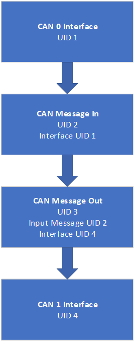
In this example, we will see how we can configure a ReXgen data logger to route all the CAN traffic from CAN 0 Bus to CAN 1 Bus
Documentation
Below image shows how each element are linked in the XML file.
image
They are connected using Unique IDs (UID).
Default Settings
CAN Baud Rate: 500 Kbps
All CAN IDs are Routed
The following parameters can be modified by editing the XML as required.
Modifying CAN Baud Rate:
Edit the value of the CANBusSpeed element in the XML file under the CAN interface block. Value has to be specified in bps
Users can load the XML file into the ReXgen logger using the ReXdesk application/ReXdesk Convert application or the Rxlibrary DLL.
The process to send XML to logger using ReXdesk. Click on Config Menu > Run > Run Config Using External File > Browse the XML file and click Open.
GitHub link
XML file
DBC file
GNSS Data Recording & Transmission Over CAN Bus.
In this example, we will see how to configure a ReXgen data logger to transmit the GNSS positioning data over the CAN Bus and record the GNSS data in the internal storage.
Following GNSS Data will be transmitted via CAN 0 Bus and recorded in internal memory:
Latitude Longitude Altitude Speed Over Ground Ground Distance Course Over Ground Number Of Satellites Quality
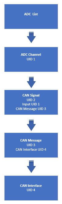
ADC Data Transmission Over CAN Bus.
This example explains configuring a ReXgen data logger to transmit the ADC data over the CAN Bus.
Following ADC Data will be transmitted via CAN 0 Bus:
ADC 0 ADC 1
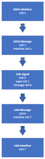
GNSS Data Transmission Over CAN Bus.
This example shows how we can configure a ReXgen data logger to transmit the GNSS positioning data over the CAN Bus.
Use Cases
Easily inject real-time location information into your CAN Bus.
The image below shows how each element is linked in the XML file.
image
They are connected using Unique IDs (UID).
Default Settings
CAN Baud Rate: 500 Kbps
GNSS Sampling Rate: 100ms
CAN ID For various signals:
0x12B – Altitude, GPS Speed
0x12C – Longitude, Latitude
0x12D – Ground Distance
0x12E – Number Of Satellites, Course
0x12F - Quality
Example DBC provided with XML.
The following parameters can be modified by editing the XML as required.
Modifying CAN Bus Channel:
Edit the value of the PhysicalNumber element in the XML file under the CAN interface block. 0 for CAN 0, 1 for CAN 1, 2 for CAN 2 and 3 for CAN 3
Modifying CAN Baud Rate:
Edit the value of the CANBusSpeed element in the XML file under the CAN interface block. Value has to be specified in bps
Modifying GNSS Sampling Rate:
Edit the value of the SamplingRate element under the GNSSINTERFACE Block
Value has to be specified in milliseconds
Modifying the CAN Identifier for the messages:
Edit the values of MessageIdentStart and MessageIdentEnd Elements under the CANMESSAGE block for the message you wish to edit. Please note that the example DBC will be invalid after this change.
Value has to be entered in Decimal
Modifying the CAN Message transmission period:
Edit the values of Period Elements under the CANMESSAGE block for the message you wish to edit.
Value has to be entered in milliseconds
Users can load the XML file into the ReXgen logger using the ReXdesk application/ReXdesk Convert application or the Rxlibrary DLL.
The process to send XML to logger using ReXdesk. Click on Config Menu > Run > Run Config Using External File > Browse the XML file and click Open.
Documentation
The below image shows how each element are linked in the XML file.
They are connected using Unique IDs (UID).
Default Settings
CAN Baud Rate: 500 Kbps
ADC Sampling Rate: 100ms
CAN ID For various signals:
0x12A – ADC 0 & ADC 1
Example DBC provided with XML.
Following parameters can be modified by editing the XML as required.
Modifying CAN Bus Channel:
Edit the value of the PhysicalNumber element in the XML file under the CAN interface block. 0 for CAN 0, 1 for CAN 1, 2 for CAN 2 and 3 for CAN 3
Modifying CAN Baud Rate:
Edit the value of CANBusSpeed element in the XML file under the CAN interface block. Value has to be specified in bps
Modifying ADC Sampling Rate:
Edit the value of SamplingRate element under the ADC list Block Value has to be specified in milliseconds
Specifying the ADC Factor and Offset:
Par A specifies the Factor, and Par B specifies the Offset.
Modifying the CAN Message transmission period:
Edit the values of MessageIdentStart and MessageIdentEnd Elements under the CANMESSAGE block for the message you wish to edit. Please note that the example DBC will be invalid after this change.
Value has to be entered in Decimal
Modifying the CAN Message transmission period:
Edit the values of Period Elements under the CANMESSAGE block for the message you wish to edit. Value has to be entered in milliseconds
User can load the XML file into the ReXgen logger using ReXdesk application/ReXdesk Convert application or the Rxlibrary DLL
Process to send XML to logger using ReXdesk. Click on Config Menu > Run > Run Config Using External File > Browse the XML file and click Open
Feed real-time location information to your CAN Dashboard or Instrument Cluster.
Use ReXgen as a GNSS module for your existing CAN data logger.
Following GNSS Data will be transmitted via CAN 0 Bus:
Latitude
Longitude
Altitude
Speed Over Ground
Ground Distance
Course Over Ground
Number Of Satellites
Quality
Documentation
The below image shows how each element is linked in the XML file.
XML_Link
They are connected using Unique IDs (UIDs).
Default Settings
CAN Baud Rate: 500 Kbps
GNSS Sampling Rate: 100ms
CAN ID For various signals:
0x12B – Altitude, GPS Speed
0x12C – Longitude, Latitude
0x12D – Ground Distance
0x12E – Number Of Satellites, Course
0x12F - Quality Example DBC provided with XML.
These parameters can be modified by editing the XML as required.
Modifying CAN Bus Channel:
Edit the value of the PhysicalNumber element in the XML file under the CAN interface block. 0 for CAN 0, 1 for CAN 1, 2 for CAN 2 and 3 for CAN 3
Modifying CAN Baud Rate:
Edit the value of the CANBusSpeed element in the XML file under the CAN interface block. Value has to be specified in bps
Modifying GNSS Sampling Rate:
Edit the value of the SamplingRate element under the GNSSINTERFACE Block Value has to be specified in milliseconds
Modifying the CAN Identifier for the messages:
noteEdit the values of MessageIdentStart and MessageIdentEnd Elements under the CANMESSAGE block for the message you wish to edit. Please not that the example DBC will be invalid after this change.
Value has to be entered in Decimal
Modifying the CAN Message transmission period:
Edit the values of Period Elements under the CANMESSAGE block for the message you wish to edit.
Value has to be entered in milliseconds
Users can load the XML file into the ReXgen logger using the ReXdesk application/ReXdesk Convert application or the Rxlibrary DLL.
The process to send XML to logger using ReXdesk. Click on Config Menu > Run > Run Config Using External File > Browse the XML file and click Open.
IMU Data Recording & Transmission Over CAN Bus.
This example shows how to configure a ReXgen data logger to transmit IMU data over the CAN Bus and record the same in eMMC storage.
Following IMU Data will be transmitted via CAN 0 Bus:
Accelerometer X Accelerometer Y Accelerometer Z
Gyroscope X Gyroscope Y Gyroscope Z
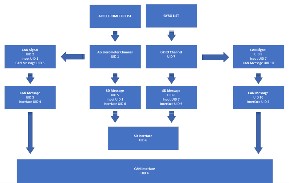
Documentation
The below image shows how each element is linked in the XML file.
They are connected using Unique IDs (UID).
Default Settings
CAN Baud Rate: 500 Kbps
ADC Sampling Rate: 100ms
CAN ID For various signals:
The following parameters can be modified by editing the XML as required.
Modifying CAN Bus Channel:
Edit the value of the PhysicalNumber element in the XML file under the CAN interface block. 0 for CAN 0, 1 for CAN 1, 2 for CAN 2 and 3 for CAN 3
Modifying CAN Baud Rate:
Edit the value of the CANBusSpeed element in the XML file under the CAN interface block.
Value has to be specified in bps
Modifying Accelerometer Sampling Rate:
Edit the value of the SamplingRate element under the ACCELEROMETER list Block.
Value has to be specified in milliseconds
Modifying Gyroscope Sampling Rate:
Edit the value of the SamplingRate element under the GYRO LIST Block
Value has to be specified in milliseconds
Modifying Accelerometer High Low Range:
Edit the value of the SamplingRate element under the ACCELEROMETER LIST Block
Value has to be specified in milliseconds
Modifying Gyroscope Sampling Rate:
Edit the value of the SamplingRate element under the GYRO LIST Block
Value has to be specified in milliseconds
Modifying the CAN Identifier for the messages:
Edit the values of MessageIdentStart and MessageIdentEnd Elements under the CANMESSAGE block for the message you wish to edit. Please note that the example DBC will be invalid after this change.
Value has to be entered in Decimal
Modifying the CAN Message transmission period:
Edit the values of Period Elements under the CANMESSAGE block for the message you wish to edit.
Value has to be entered in milliseconds
Users can load the XML file into the ReXgen logger using the ReXdesk application/ReXdesk Convert application or the Rxlibrary DLL.
The process to send XML to logger using ReXdesk. Click on Config Menu > Run > Run Config Using External File > Browse the XML file and click Open.
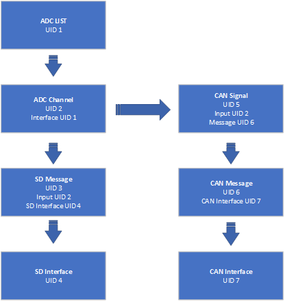
In this example, we will see how we can configure a ReXgen data logger to transmit the ADC data over the CAN Bus and record the ADC data in the internal storage.
Following ADC Data will be transmitted via CAN 0 Bus and recorded in internal memory:
ADC 0 ADC 1
RTC Data To CAN Bus
This example explains configuring a ReXgen data logger to transmit the RTC data over the CAN Bus.
Documentation
Documentation
The below image shows how each element is linked in the XML file.
image
They are connected using Unique IDs (UID).
Default Settings
CAN Baud Rate: 500 Kbps
ADC Sampling Rate: 100ms
CAN ID For various signals:
0x12A – ADC 0 & ADC 1
Example DBC provided with XML.
The following parameters can be modified by editing the XML as required.
Modifying CAN Bus Channel:
Edit the value of the PhysicalNumber element in the XML file under the CAN interface block. 0 for CAN 0, 1 for CAN 1, 2 for CAN 2 and 3 for CAN 3
Modifying CAN Baud Rate:
Edit the value of the CANBusSpeed element in the XML file under the CAN interface block. Value has to be specified in bps
Modifying ADC Sampling Rate:
Edit the value of the SamplingRate element under the ADC list. Block Value has to be specified in milliseconds
Specifying the ADC Factor and Offset:
Par A specifies the Factor, and Par B specifies the Offset.
Modifying the CAN Identifier for the messages:
Edit the values of MessageIdentStart and MessageIdentEnd Elements under the CANMESSAGE block for the message you wish to edit. Please note that the example DBC will be invalid after this change.
Value has to be entered in Decimal
Modifying the CAN Message transmission period:
Edit the values of Period Elements under the CANMESSAGE block for the message you wish to edit.
Value has to be entered in milliseconds
The user can load the XML file into the ReXgen logger using the ReXdesk application/ReXdesk Convert application or the Rxlibrary DLL.
The process to send XML to logger using ReXdesk. Click on Config Menu > Run > Run Config Using External File > Browse the XML file and click Open.
The below image shows how each element is linked in the XML file.
They are connected using Unique IDs (UID).
Default Settings:
CAN Baud Rate: 500 Kbps
Example DBC provided with XML.
The following parameters can be modified by editing the XML as required.
Modifying MaxlogSize and MaxLogTime:
Edit the values of MaxLogSize and MaxLogTime (in seconds) Elements under the SDINTERFACE block for the message you wish to edit.
Modifying CAN Bus Channel:
Edit the value of the PhysicalNumber to change the channel number to 0, 1, 2 or 3
Modify the CANBusSpeed element in the XML file under the CAN interface block to modify the CAN bus baud rate.
Value has to be specified in bps
Modifying the CAN Message and Transmission period:
Edit the MessageIdentStart and MessageIdentEnd Elements values under the CANMESSAGE block for the message ID you wish to transmit to the RTC.
Modify the Transmission period by editing the value of the Period in the XML.
Please note that the example DBC will be invalid after this change.
Modifying the Sampling Rate:
Edit the values of the Sampling Rate under the INTERNAL_PARAMETER block for the message you wish to edit. Please note that the example DBC will be invalid after this change.
Modifying the CAN Signal:
Edit the StartBit and Bit Count Elements values under the CANSIGNAL block for the message you wish to edit. Please note that the example DBC will be invalid after this change.
Users can load the XML file into the ReXgen logger using the ReXdesk application/ReXdesk Convert application or the Rxlibrary DLL.
The process to send XML to logger using ReXdesk. Click on Config Menu > Run > Run Config Using External File > Browse the XML file and click Open.
IMU Data Transmission Over CAN Bus.
This example shows configuring a ReXgen data logger to transmit IMU data over the CAN Bus.
Following IMU Data will be transmitted via CAN 0 Bus:
The below image shows how each element is linked in the XML file.
They are connected using Unique IDs (UID).
Default Settings
CAN Baud Rate: 500 Kbps
ADC Sampling Rate: 100ms
CAN ID For various signals:
0x128 – Accelerometer
0x129 – Gyroscope
Example DBC provided with XML.
Following parameters can be modified by editing the XML as required.
Modifying CAN Bus Channel:
Edit the value of the PhysicalNumber element in the XML file under the CAN interface block. 0 for CAN 0, 1 for CAN 1, 2 for CAN 2 and 3 for CAN 3
Modifying CAN Baud Rate:
Edit the value of CANBusSpeed element in the XML file under the CAN interface block.
Value has to be specified in bps
Modifying Accelerometer Sampling Rate:
Edit the value of SamplingRate element under the ACCELEROMETER list Block.
Value has to be specified in milliseconds
Modifying Gyroscope Sampling Rate:
Edit the value of the SamplingRate element under the GYRO LIST Block
Value has to be specified in milliseconds
Modifying Accelerometer High Low Range:
Edit the value of the SamplingRate element under the ACCELEROMETER LIST Block
Value has to be specified in milliseconds
Modifying Gyroscope Sampling Rate:
Edit the value of the SamplingRate element under the GYRO LIST Block
Value has to be specified in milliseconds
Modifying the CAN Identifier for the messages:
Edit the values of MessageIdentStart and MessageIdentEnd Elements under the CANMESSAGE block for the message you wish to edit. Please note that the example DBC will be invalid after this change.
Value has to be entered in Decimal
Modifying the CAN Message transmission period:
Edit the values of Period Elements under the CANMESSAGE block for the message you wish to edit.
Value has to be entered in milliseconds
Users can load the XML file into the ReXgen logger using the ReXdesk application/ReXdesk Convert application or the Rxlibrary DLL.
The process to send XML to logger using ReXdesk. Click on Config Menu > Run > Run Config Using External File > Browse the XML file and click Open.