LogoLogo
Home
  • 🏠Home
  • K-Series: Product Manual
    • K-Box: Product Manual
      • Connecting and powering the K-Box
        • Enable the AUX Power setting within the Logger Configuration
      • Configuring the K-Box
        • Installing the Kvaser Drivers
        • Installing ReXgen J2534 Drivers
        • Installing the Rebel Drivers
        • Installing the K-Cal Software
        • Using the K-Cal Software
          • Configuring the Analog Channels
          • Configuring the Digital Channels
            • The Input Function
            • Pulse Duration Measurement
            • Frequency Measurement
            • High-Frequency measurement
            • Cycle Duration Measurement
            • Duty Cycle/PWM Measurement
            • Event Measurement
            • RPM Measurement
            • The Output Function
          • Reprogramming the K-Box
          • Calibrating the K-Box
          • Erasing the Calibration
      • Using K-Box Cal to display data
        • Channel Display and Conversion
          • Selecting the Channel to display
          • Creating a Conversion Table
          • Applying a Conversion Table to a Channel
          • Applying a Formula to a Channel
        • Using the Oscilloscope to display data
          • Individually Adding items to the Oscilloscope.
          • Adding All Channels to the Oscilloscope (Method 1)
          • Adding All Channels to the Oscilloscope (Method 2)
          • Working with items added to the Oscilloscope
        • Using the Oscilloscope
        • Exporting a DBC file with conversion tables and Formulas
      • Making a Configuration in Dialog to Log K-Box
      • Appendix
        • Specifications
        • Pinout of the K Box
        • Pinout of the Multi Connect Cable
        • Measurement IEPE procedure
    • K-TC: User Quick Start Guide
      • Getting Started
        • Pinout details
        • Software Installation
        • Driver Installation
      • Software Introduction
        • Graphical Overview
        • Navigation Bar
        • Status Bar
        • Configuration Panel
        • Max Log Time (min)
        • Internal Storage Window
        • Show Data Log Window
      • The 'How to' Guide
        • Preparation of configuration
        • Setting up Max log time
        • Retrieving the Datalog
    • K-TC: Logger Manual
      • Introduction
        • Technical Specifications
        • Pinout of the K-TCxx
        • Software Installation
          • Installing the K-TCxx Cal Software
          • K-TCxx Driver installation
          • Installing the Rebel Drivers
      • Connecting and powering the K-TCxx
        • Enable the AUX Power setting within the Logger Configuration
      • Software Introduction
        • Interface Tab
          • General Tab
          • Measurement Tab
          • Thermo Couples Tab
          • Calibration
          • Reprogramming
          • Manufacturer
      • Using the K-TCxx Cal Software
        • Reprogramming the K-TCxx
        • Calibrating the K-TCxx
        • Erasing the Calibration
        • Configuring the K-TCxx
        • Using K-TCxx Cal to display data
        • Channel Display
        • Selecting the Channel to display
      • Using the Oscilloscope to display data
        • Individually Adding items to the Oscilloscope.
        • Adding All Channels to the Oscilloscope (Method 1)
        • Adding All Channels to the Oscilloscope (Method 2)
        • Working with items added to the Oscilloscope
        • Using the Oscilloscope
      • Exporting a DBC file
      • Loading the K-TCxx configuration into DiaLog
      • Appendix
    • K-TC 2.0: User Quick Start Guide (using K-Log)
      • Getting Started
        • Pinout details
        • Software Installation
        • Driver Installation
      • Software Introduction
        • Graphical Overview
        • Navigation Bar
        • Status Bar
        • Configuration Panel
        • Max Log Time (min)
        • Internal Storage Window
        • Show Data Log Window
      • The 'How to' - Guide
        • Preparation of configuration
        • Setting up Max log time
        • Retrieving the Datalog
    • K-TC 2.0 : Logger Manual (using K-CAL)
      • Introduction
        • Technical Specifications
        • Pinout of the K-TCxx
        • Software Installation
          • Installing the K-TCxx Cal Software
          • K-TCxx Driver installation
          • Installing ReXgen J2534 Drivers
          • Installing the Rebel Drivers
      • Connecting and powering the K-TCxx
        • Enable the AUX Power setting within the Logger Configuration
      • Software Introduction
        • Interface Tab
          • General Tab
          • Measurement Tab
          • Thermo Couples Tab
          • Calibration
          • Reprogramming
          • Manufacturer
      • Using the K-TCxx Cal Software
        • Reprogramming the K-TCxx
        • Calibrating the K-TCxx
        • Erasing the Calibration
        • Configuring the K-TCxx
        • Using K-TCxx Cal to display data
        • Channel Display
        • Selecting the Channel to display
      • Using the Oscilloscope to display data
        • Individually Adding items to the Oscilloscope.
        • Adding All Channels to the Oscilloscope (Method 1)
        • Adding All Channels to the Oscilloscope (Method 2)
        • Working with items added to the Oscilloscope
        • Using the Oscilloscope
      • Exporting a DBC file
      • Loading the K-TCxx configuration into DiaLog
      • Appendix
  • Pinouts for K-Series devices
    • K Box Pinouts (INF 2201)
    • KTC-XX Pinouts (INF 2204.02/5.02/6.02)
    • K AN8 Pinouts (INF 2210)
    • K IEPE Pinouts (Add-On) (INF 2213)
    • K PT Pinouts (Add-On) (INF 2212)
    • Appendix
      • The Wake Up Pin
      • Digital Input function
      • Digital Output function
Powered by GitBook
On this page
Export as PDF
  1. K-Series: Product Manual
  2. K-TC 2.0 : Logger Manual (using K-CAL)
  3. Software Introduction
  4. Interface Tab

Thermo Couples Tab

PreviousMeasurement TabNextCalibration

Last updated 11 months ago

Users can configure the CAN ID, Transmission rate and thermocouple type in this window.

Pressing the Load Button Loads the settings in the K-TCxx and displays them on the screen.
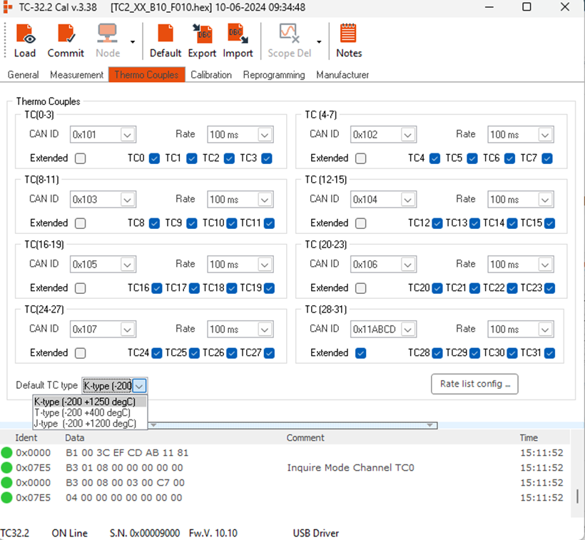
CAN ID

Users can use this option to set the CAN ID of the messages containing thermocouple data

Rate

Allows the user to set the CAN message transmission rate.

Type

Allows the user to select the thermocouple type.

Rate List Config

Allows the user to add additional transmission rates.

Pressing the Default Button will reset all the settings.

Pressing DBC Export will open the DBC export window.

Pressing the Import button will load the settings from the DBC file.

Pressing the 'Notes' button will open the release notes containing all the details about the software's development.