# Hardware
### Installation
The contents below specify the conditions required for the operation of ReXgen1.
**GROUNDING**
Since providing a common ground between nodes is not required, it is possible to have ground offsets between nodes. Each node may observe different single-ended bus voltages (common mode bus voltages) while maintaining the same differential voltage. Operating a CAN system with large ground offsets can increase electromagnetic emissions. If the system is sensitive to emissions, steps must be taken to eliminate ground offsets.
**TERMINATION**
ISO-11898 requires that the CAN bus have a nominal characteristic line impedance of 120Ω. Therefore, the typical terminating resistor value for each bus end is 120Ω. Bus termination is used to minimise signal reflection on the bus.
**SUPPLY VOLTAGE**
It is always recommended to keep the nominal voltage within the specified range. The device also has internal protection against low-energy voltage events due to supply wire noise.
**ISOLATION**
CAN Bus and USB are not isolated; care must be taken when plugging the USB into the device. Removing the power supply when the device is interfaced with a PC via a Micro USB cable is advised.
{% hint style="warning" %}
**Notes:**
* The CAN Bus Isolator and USB Isolators can be purchased separately.
* Please do not use the logger's USB port for data logging, as it may damage the port and will not be covered under warranty.
{% endhint %}
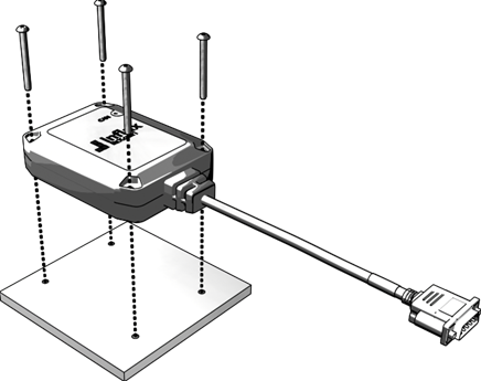
**MOUNTING**
Always mount the device in a way that minimises vibration exposure and accounts for its IP rating. ReXgen1 includes four screws to assist with mounting.